![Upwards and downward gaze [4]](figures/fig1.gif)
![Sideways Gaze [4]](figures/fig2.gif)
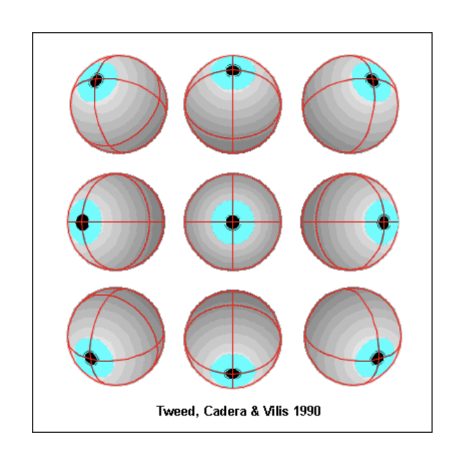
![Torsional Rotations [4]](figures/fig3.gif)
Rotation about each axis is represented by a matrix:
$$ R_3(\theta) = \begin{bmatrix} \cos\theta & -\sin\theta & 0 \\ \sin\theta & \cos\theta & 0 \\ 0 & 0 & 1 \end{bmatrix} $$ $$ R_2(\phi) = \begin{bmatrix} \cos\phi & 0 & \sin\phi \\ 0 & 1 & 0 \\ -\sin\phi & 0 & \cos\phi \end{bmatrix} $$ $$ R_1(\psi) = \begin{bmatrix} 1 & 0 & 0 \\ 0 & \cos\psi & -\sin\psi \\ 0 & \sin\psi & \cos\psi \end{bmatrix} $$A general rotation is then given by:
$$ R = R_3(\theta) R_2(\phi) R_1(\psi) $$Any general rotation can then be defined by multiplying the rotation matrices above. \[ R = R_3(\theta) R_2(\phi)R_1(\psi) \] \[ R = \left[ \begin{matrix} \cos(\theta)\cos(\phi) & \cos(\theta)\sin(\phi)\sin(\psi) - \sin(\theta)\cos(\psi) & \cos(\theta)\sin(\phi)\cos(\psi) + \sin( \theta)\sin(\psi) \\ \sin(\theta)\cos(\phi) & \sin(\theta)\sin(\phi)\sin(\psi) + \cos(\theta)\cos(\psi) & \sin(\theta)\sin(\phi)\cos(\psi) - \cos( \theta)\sin(\psi) \\ - \sin(\phi) & \cos(\phi)\sin(\psi) & \cos(\phi)\cos(\psi) \end{matrix}\right] \]
It is possible to describe the rotation of the eye-fixed coordinate system from the reference position to any new position using the general rotation matrix. This is an intrinsic rotation about z-y-x axes. The order for matrix multiplication is from right to left and desired final eye position vector is dependent on the order since matrix multiplication is non-commutative. This can produce undesired effects.
The general rotation matrix R still completely describes the current eye position. However, its elements are no longer determined by the relatively simple formulas.

[A] 90° rotation about the vertical axis h3, followed by a 90° rotation about the horizontal axis h2.
[B] 90° rotation about the horizontal axis h2, followed by a 90° rotation about the vertical axis h3.
[C] 90° rotation about the eye-fixed axis e2, followed by a 90° rotation about the eye-fixed axis e3.
To understand this better, we look at the above figure taken from Thomas Haslwanter (1995) Mathematics of three-dimensional eye rotations 2. Inverting the sequence of two rotations about space-fixed axes changes the final orientation of the object, even if it is rotated by the same degree [2]. The final orientation of the figure in [A] differs from that of [B] due to the non commutativity of the Rotation Matrix.
However, it is also possible to reach the same final orientation by two different sequences of rotations, as is the case for [A] and [C].
Donder’s Law
The proposition that for any head position and any direction of gaze the eye always assumes the same unique position, resulting in the fixation point being focused on the fovea. The orientation is always the same no matter where the eye came from.
In order to implement Donder’s law, it is important to find a unique method to reach every final orientation or the final eye position. If the previously mentioned rotation matrix method is followed, there are six possible sequence of rotations arising from the three rotation axes, some of which reach the same orientation as the other sequence.
The Gimbal Arrangement
One of the simplest solutions to Donder’s law is to nest coordinate systems and describe rotations in either a head-fixed or eye-fixed coordinate system. Such a coordinate system is known as gimballed coordinate system. There is an infinite number of possible coordinate systems that fulfill this condition. However, for ease, a vertical and a horizontal nested system is almost always chosen. The Gimballed systems - Fick's and Helmholtz, are represented in the below figure.
![Demonstration of the Gimbal coordinate system [3]](figures/gimbal.png)
Nested Gimbal systems such as the ones mentioned below, fix a nesting order for the decomposition of a three-dimensional rotation into three consecutive rotations. There is, in fact, a third and even simpler way of describing a three-dimensional rotation that does not depend on the order of rotations. This is rotation along an orthogonal axis of the eye.
Fick’s System
Fick’s gimbal coordinate system can be used for eye tracking experiments where the head is immobilized using a chin rest. The sequence of rotation is horizontal, vertical, and torsional or in terms of our previous notations; yaw, pitch and roll. 1
\[ R_{Fick} = R_3(\theta_F)R_2(\phi_F)R_1(\psi_F) \]Helmholtz System
Another commonly used system in the past is the Helmholtz system that differs from the Fick’s system as it prefers the vertical axis over the horizontal axis. The sequence of rotation is pitch, yaw and roll about the new line of sight. 1
\[R_{Helmholtz} = R_3(\phi_H)R_2(\theta_H)R_1(\psi_H) \]Euler Fixed Axis Theorem
Euler’s rotation theorem states that in a three-dimensional space, any displacement of a rigid body such that a point on the rigid body remains fixed, is equivalent to a single rotation about some axis that runs through the fixed point.
Following this, a three dimensional rotation can now just be described using a vector that points in the direction of rotation. Similar to the rotation matrices, the direction of the rotation should follow the right hand thumb rule as convention. Now, simply three elements of rotations are necessary to quantify a three dimensional rotation unlike the nine elements for matrix rotations.
![Demonstration of the Euler Fixed Axis Theorem [6]](figures/euler.png)
Every final eye position can be described by a unique rotation vector that denotes a rotation from an initial primary eye position.
Rotation vectors can also have horizontal, vertical, and torsional components, and the two most effective mathematical treatments of such simplified rotations are the quaternions and rotation vectors.
Quaternions
To represent rotations in three dimensions, we can use a quaternion, q which uniquely characterizes a rotation by an angle \( \theta \) about an axis \( \hat{n} \). Such a number system extends the complex numbers.
![Quaternion [5]](figures/quat.png)
The quaternion has a scalar \( (q_0) \) and a vector component(q). The length of the vector is determined by the angle \(\theta \), which allows us to rewrite it as -
\[ q = \cos(\theta/2) + \sin(\theta/2)\left( n_x\hat{i} + n_y\hat{j} + n_z\hat{k} \right)\]Further description and interactive videos for an in-depth understanding of quaternions can be found on the explorable video series webpage by Ben Eater.
Rotation Vectors
To make the treatment simpler, we notice that the scalar component of a unit quaternion \( (q_0) \) does not contain any additional information, that is not already given by the vector part [2] . The rotation vector then is just a simplified quaternion given by the equation
\[ r = \frac{\mathbf{q}}{q_0}\] \[ r= \tan(\theta/2)\hat{n} \]Listing’s Law
A special realization of Donder’s law is Listing’s law. Listing’s law brings about a constraint in the three dimensional motion of the eyes and reduces it to almost a two dimensional problem. It states that any final orientation taken by the eye can be reached by rotation about an axis that lies within Listing’s plane. Listing’s plane is a two-dimensional plane orthogonal to the gaze direction of the primary position of the eye. (not the initial position of the eye but the primary position).
![Listing’s plane [4]](figures/listing.png)
The reference position for a dataset that describes the Listing's plane as its displacement plane is called the primary position. This displacement plane will be exactly perpendicular to the reference gaze direction. For humans, this primary position is most commonly when the eye is looking straight ahead with the visual axis parallel to the sagittal plane of the head.
Essentially, Listing’s law defines zero torsion about a head-fixed axis. It is however possible to reach this final orientation described by Listing's using the eye-fixed axes such Helmholtz sequence and Fick’s sequence of rotations by the introduction of false torsion along the line of sight.
However, the simplest way to implement the Listing’s law would be using a coordinate axis with origin at the primary position (1, 0, 0) where the torsional component of the head is held at zero.
One of the advantages of using quaternion or rotation vector formalism is the ease of implementing Listing’s law with these tools. The complete rotation vector in accordance to the Listing’s law can then be written as
\[ \vec{r} = \tan(\theta/2)\hat{n}\] \[ \vec{r} = \tan(\theta/2)\left(\begin{matrix} 0 \\ \cos(\alpha) \\ - \sin(\alpha) \end{matrix}\right)\]Where, \( \alpha \) describes the orientation of the rotation vector within Listing’s plane as explained in Listing’s law and the mathematics of eye. This rotation vector describes the rotation of the point from a primary position to a final position with zero torsional component. The validity of Listing’s law can also be checked by checking if all these rotation vectors lie in the same displacement plane known as the Listing's plane
Three-Dimensional Rotations According to Listing's Law
The GitHub repository consists of a set of source code that allows users to simulate the initial and final positions of the eye taking into account Listing's and Donder's law. The program also allows the users to visualize the final complete rotational vectors to check if they lie within the Listing's plane.
References
- Adelson, E. H., & Bergen, J. R. (1985). Spatiotemporal energy models for the perception of motion. JOSA A, 2(2), 284–299.
- Haslwanter, T. (1995). Mathematics of three-dimensional eye rotations. Vision Research, 35(12), 1727–1739.
- Quaia, C., & Optican, L. M. (2001). Three-dimensional rotations of the eye.
- Tweed, D., & Vilis, T. (1990). Geometric relations of eye position and velocity vectors during saccades. Vision Research, 30, 111–127.
- van der Waerden, B. L. (1976). Hamilton’s discovery of quaternions. Mathematics Magazine, 49(5), 227–234.
- Wikipedia contributors. Euler’s rotation theorem — Wikipedia.
- Wikipedia contributors. Rotation matrix — Wikipedia.